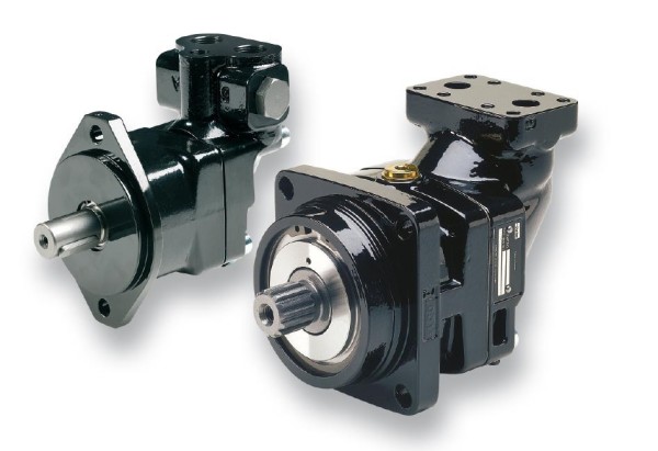
Hydraulic Motor/Pump
Series F11/F12
Fixed Displacement
Conversion factors
1 kg.................................................................. 2.20 lb
1 N................................................................ 0.225 lbf
1 Nm.......................................................... 0.738 lbf ft
1 bar...............................................................14.5 psi
1 l.......................................................0.264 US gallon
1 cm3 ........................................................0.061 cu in
1 mm.............................................................. 0.039 in
9/5°C + 32.............................................................1°F
1 kW............................................................... 1.34 hp
Content Page
General information...............................................................................4
F11 cross section..................................................................................4
F12 cross sections.................................................................................5
Specifications........................................................................................6
Ordering codes ....................................................................................7
F11-CETOP...........................................................................................7
F11-ISO.................................................................................................8
F11-SAE................................................................................................9
F12-ISO...............................................................................................10
F12-Cartridge, CETOP........................................................................11
F12-SAE..............................................................................................12
Preferred versions F11/F12.................................................................13
Technical information
Bearing life...........................................................................................14
Efficiency.............................................................................................15
Noise level...........................................................................................15
Selfpriming speed and required inlet pressure....................................16
Installation dimensions
F11-5 CETOP......................................................................................17
F11-6, -10 CETOP...............................................................................18
F11-12 CETOP....................................................................................19
F11-14 CETOP....................................................................................20
F11-19 CETOP....................................................................................21
F11-10 ISO..........................................................................................22
F11-12 ISO..........................................................................................23
F11-14 ISO..........................................................................................24
F11-10 SAE.........................................................................................25
F11-12 SAE.........................................................................................26
F11-14 SAE.........................................................................................27
F11-19 SAE.........................................................................................28
F12-30, -40, -60, -80, -90, -110 and -125 ISO....................................30
F12-30, -40, -60, -80, -90, -110 and -125 Cartridge............................32
F12-30, -40, -60, -80, -90, -110 and -125 SAE 4 bolt flange...............34
F12-30, -40, and -60 2 bolt flange.......................................................36
F12-150 CETOP..................................................................................38
F12-150 SAE.......................................................................................39
F12-250 SAE.......................................................................................40
Technical information
F11 in saw motor applications.............................................................41
Series F11iP........................................................................................41
F11 and F12 fan motors......................................................................43
Flushing valves for F12 motors............................................................44
FV13 flushing valve block ...................................................................45
SR pressure relief / make-up valve......................................................46
SP super shockless, pressure relief valve ..........................................49
Speed sensor......................................................................................51
Installation information
Direction of rotation.............................................................................52
Hydraulic fluids....................................................................................52
Operating temperature........................................................................52
F11/F12 in series operation ................................................................52
Viscosity..............................................................................................53
Filtration...............................................................................................53
Case pressure.....................................................................................53
Case drain connections.......................................................................54
Before start-up.....................................................................................54
|